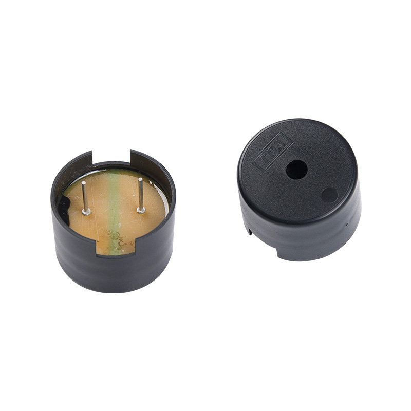
The drive circuit design of a piezo buzzer needs to consider several points to ensure that the buzzer can work stably and emit the required sound. Here are some key factors to consider when designing a piezo buzzer driver circuit:
Resonant Frequency Matching: piezo buzzer s are designed to operate at a specific resonant frequency for maximum sound output. The driver circuit must be able to generate a signal that matches the buzzer's resonant frequency. This usually involves measuring the resonant frequency of the buzzer and designing an oscillator or multivibrator circuit to generate a signal at the corresponding frequency.
Waveform generation: piezo buzzer s require square wave signals to drive because square wave signals effectively vibrate piezoelectric materials. When designing a circuit, you can use the PWM (Pulse Width Modulation) output of a microcontroller or a specialized oscillator circuit to generate the desired square wave signal.
Power supply voltage and current driving capability: The driving circuit should be compatible with the operating voltage range of the piezo buzzer and be able to provide sufficient current. Since a piezo buzzer may require a large instantaneous current when activated, the circuit design should take this into account, and may require the use of transistors or integrated circuits with sufficient driving capabilities.

Power Consumption vs. Efficiency: In battery-powered devices, power consumption is a critical design parameter. Driver circuits should be designed to be as efficient as possible to reduce energy consumption and extend battery life. This may involve using low-power logic circuits and optimizing power management.
Noise suppression and electromagnetic compatibility: To reduce electromagnetic interference (EMI), it may be necessary to add filters or shielding to the circuit. In addition, circuit design should comply with relevant electromagnetic compatibility standards to ensure that there is no interference with other equipment.
Protection measures: The drive circuit should include overvoltage and overcurrent protection to prevent buzzer damage caused by power fluctuations or circuit failures. This can be achieved by using appropriate protection diodes, transistors or integrated circuits.
Debugging and Testing: The design should be easy to test and debug. For example, you could include potentiometers for adjusting frequency and volume, or use a microcontroller with programmable outputs to adjust parameters without changing the hardware.
By comprehensively considering the above points, a piezo buzzer drive circuit can be designed that meets the performance requirements and is cost-effective, ensuring that the buzzer can work reliably in various applications.


 EN
EN  English
 Deutsch
 中文简体
中文简体
